
Assembly Instructions
This document describes the process on how to install one sheet LED harness assembly assistant board.
The type of pieces that are going to be use are divided into three types for easier understanding (Accessories, Straight boards, and Curve boards)
List of Materials
| Name | Description | Type | Quantity |
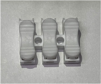
| Foled-SC-3P | Smart connector with 3 plugs for 5V, GND and Data | Accessory | 20 pcs + 5 extras |
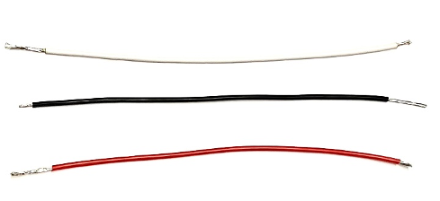
| Foled-CA-3S | Set of three 20AWG cables (one red, one white and one black) | Accessory | 12 pcs + 3 extras |
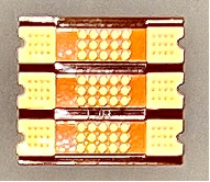
| Foled-FB-3P | Flexible PCB connector board | Accessory | 5 pcs + 2 extras |
| Foled-S-145 | A set of three straight boards (S-49+S-48+S-48) | Straight boards | 1 pc |
| Foled-S-144 | A set of three straight boards (S-48+S-48+S-48) | Straight boards | 6 pcs |
| Foled-S-120 | A set of three straight boards (S-48+S-48+S-24) | Straight boards | 1 pc |
| Foled-S-96 | A set of two straight boards (S-48+S-48) | Straight boards | 5 pcs |
| Foled-S-72 | A set of two straight boards (S-48+S-24) | Straight boards | 1 pc |
| Foled-A6-72 | One curve board with 72 leds | Curve boards | 1 pc |
| Foled-A5-72 | One curve board with 72 leds | Curve boards | 1 pc |
| Foled-A4-72 | One curve board with 72 leds | Curve boards | 1 pc |
| Foled-A3-60 | One curve board with 60 leds | Curve boards | 1 pc |
| Foled-A2-60 | One curve board with 60 leds | Curve boards | 1 pc |
| Foled-A1-96 | One curve board with 96 leds | Curve boards | 1 pc |
| Foled-B5-96 | One curve board with 96 leds | Curve boards | 1 pc |
| Foled-B4-96 | One curve board with 96 leds | Curve boards | 1 pc |
| Foled-B3-58 | One curve board with 58 leds | Curve boards | 1 pc |
| Foled-B2-62 | One curve board with 62 leds | Curve boards | 1 pc |
| Foled-B1-72 | One curve board with 72 leds | Curve boards | 1 pc |
Accessories
These pieces are used to help connect the different led boards between each other.
Straight boards
All these boards are ready to be use out of the box.
Foled-S-145
This board is made from one Foled-S-49 and two Foled-S-48 by soldering Foled-FB-3P between each board.

Foled-S-144
This board is made from three Foled-S-48 by soldering Foled-FB-3P between each board.

Foled-S-120
This board is made from two Foled-S-48 and one Foled-S-24 by soldering Foled-FB-3P between each board.

Foled-S-96
This board is made from two Foled-S-48 by soldering Foled-FB-3P between them.

Foled-S-72
This board is made from one Foled-S-48 and one Foled-S-24 by soldering Foled-FB-3P between them.

Curve boards
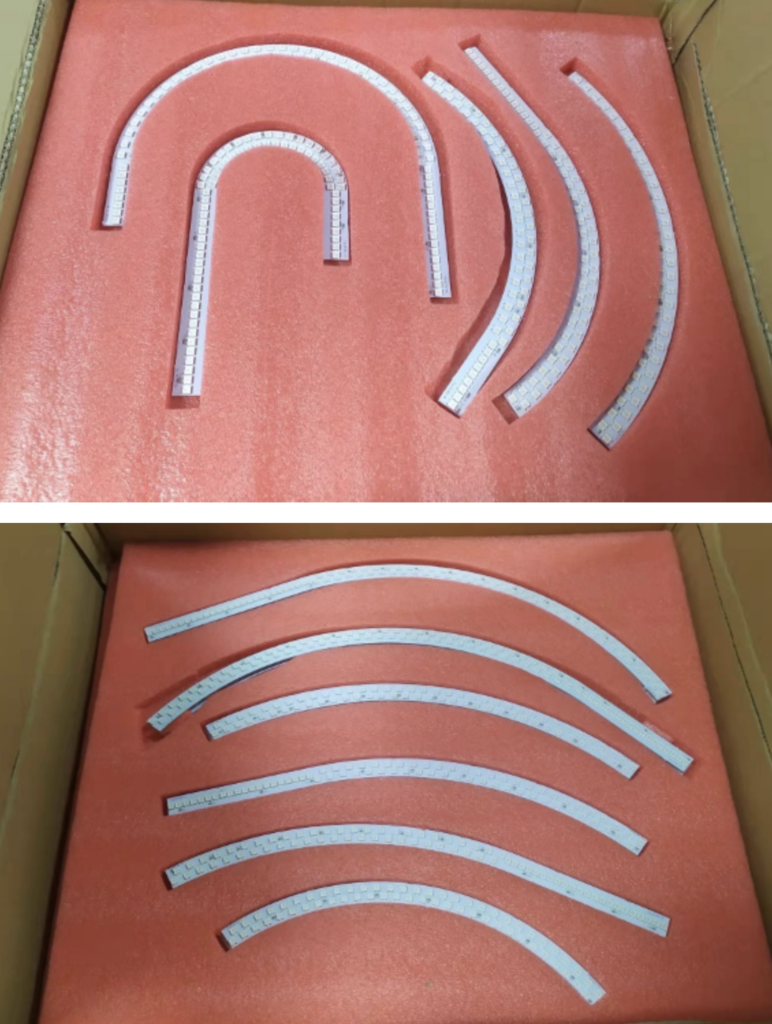
These pieces need to be assembled into sets by soldering the accessories which will be described below. They can be identified by their name at the beginning and end of the board. There is a total of 11 unique pieces:
- Foled-A6-72
- Foled-A5-72
- Foled-A4-72
- Foled-A3-60
- Foled-A2-60
- Foled-A1-96
- Foled-B5-96
- Foled-B4-96
- Foled-B3-58
- Foled-B2-62
- Foled-B1-72
Set A6, A5 and A4
This process shows how to connect these three led boards together to make one single piece.
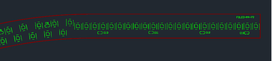
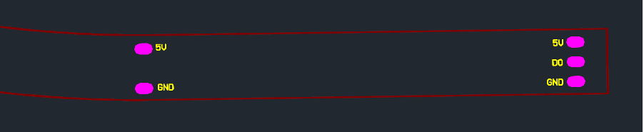
Step 1 (piece Foled-A4-72)
Solder one cable on each pad (5V: red cable, DO: white cable, GND: black cable) pointing to the inside of the board as it shows the blue arrow.
Top View
Bottom View

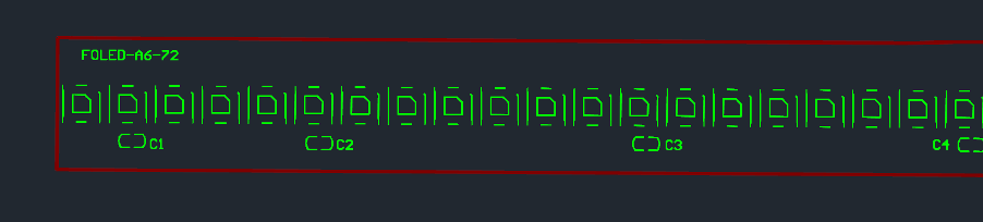
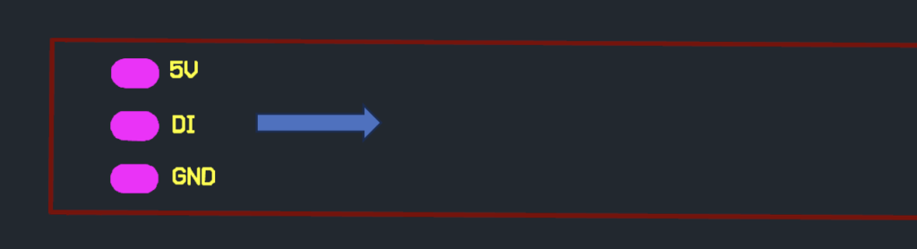
Step 2 (piece Foled-A6-72)
Solder one cable on each pad (5V: red cable, DI: white cable, GND: black cable) pointing to the inside of the board as it shows the blue arrow.
Top View
Bottom View

Step 3 (piece Foled-A5-72)
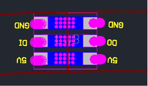
Solder Foled-FB-3P connector board to both sides of the led board
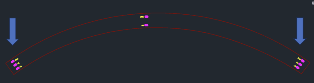
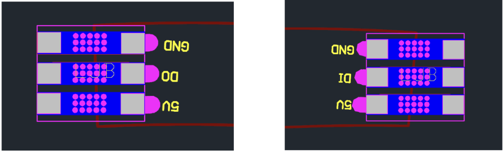
Note: make sure Foled-FB-3P connector board is aligned to the half part of each pad as it shows in the drawing above.
Step 4
Connect one end of A5-72 (output) to the input of A4-72 by soldering it to the other part of Foled-FB-3P connector as shows in the diagram below:
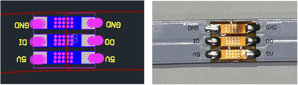
Step 5
Connect the other end of A5-72 (input) to the output of A6-72 (same process as above). After this process is completed there should be one big piece like this drawing, with cables at both ends and two Foled-FB-3P (FPS) connector boards.
Bottom View
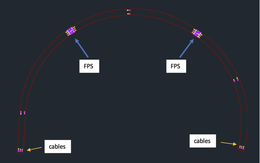
Note: if for assembly reasons is better to have the three pieces separated, then the FPS connector board can be replaced by cables.
Set A2 and A3
This process shows how to connect these two led boards together to make one single piece.
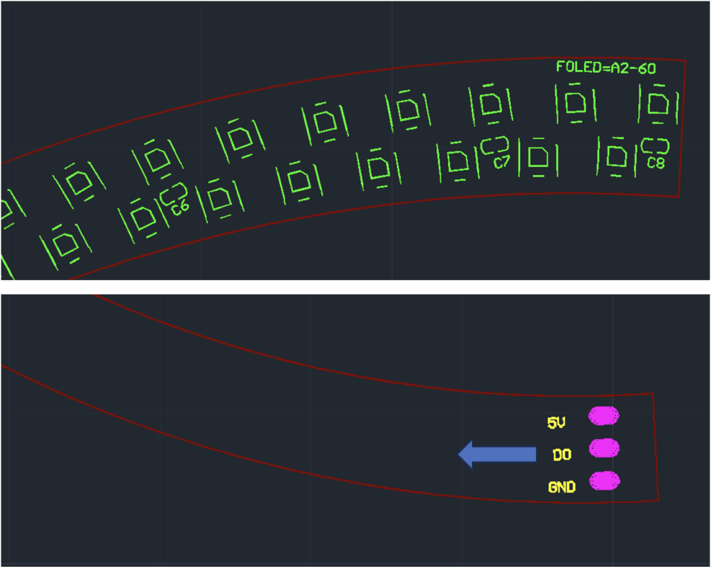
Step 1 (piece Foled-A2-60)
Solder one cable on each pad (5V: red cable, DO: white cable, GND: black cable) pointing to the inside of the board as it shows the blue arrow.
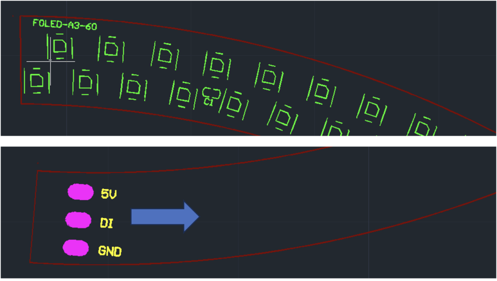
Step 2 (piece Foled-A3-60)
Solder one cable on each pad (5V: red cable, DI: white cable, GND: black cable) pointing to the inside of the board as it shows the blue arrow.
Step 3
Connect one end of A2-60 (output) to the input of A3-60 by soldering it to the other part of Foled-FB-3P connector as shows in the diagram below:
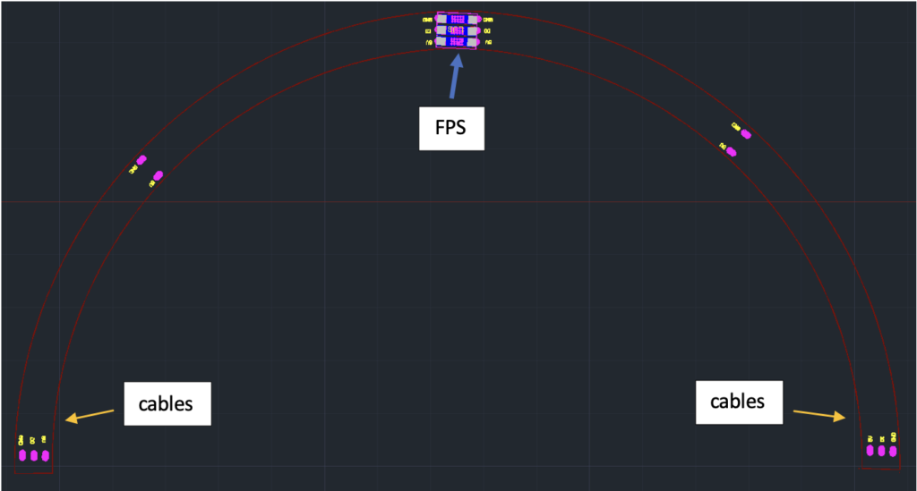
After this process is completed there should be one big piece like this drawing, with cables at both ends and one Foled-FB-3P (FPS) connector board at the middle of the two led boards.
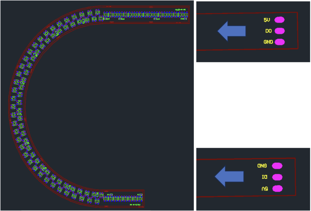
A1-96 (Single piece)
Solder one cable on each pad (5V: red cable, DI/DO: white cable, GND: black cable) pointing to the inside of the board as it shows the blue arrow. Cables should be soldered in both ends of the led board.
Set B4 and B5
This process shows how to connect these two led boards together to make one single piece.
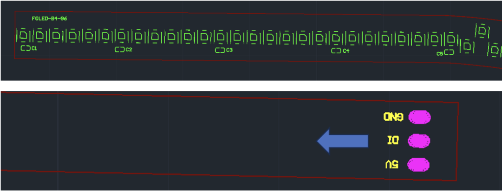
Step 1 (piece Foled-B4-96)
Solder one cable on each pad (5V: red cable, DI: white cable, GND: black cable) pointing to the inside of the board as it shows the blue arrow.
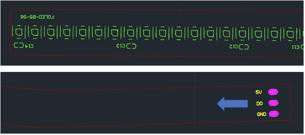
Step 2 (piece Foled-B5-96)
Solder one cable on each pad (5V: red cable, DO: white cable, GND: black cable) pointing to the inside of the board as it shows the blue arrow.
Step 3
Connect one end of B4-96 (output) to the input of B5-96 by soldering it to the other part of Foled-FB-3P connector as shows in the diagram below:
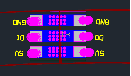
After this process is completed there should be one big piece like this drawing, with cables at both ends and one Foled-FB-3P (FPS) connector board at the middle of the two led boards.
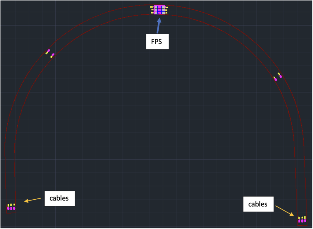
Set B2 and B3
This process shows how to connect these two led boards together to make one single piece.
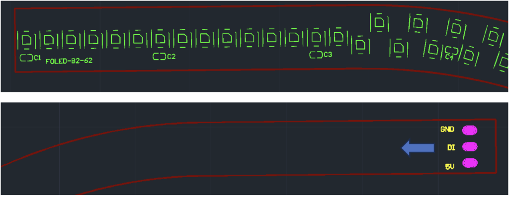
Step 1 (piece Foled-B2-62)
Solder one cable on each pad (5V: red cable, DI: white cable, GND: black cable) pointing to the inside of the board as it shows the blue arrow.
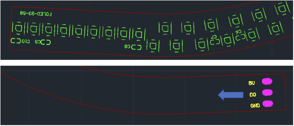
Step 2 (piece Foled-B3-58)
Solder one cable on each pad (5V: red cable, DO: white cable, GND: black cable) pointing to the inside of the board as it shows the blue arrow.
Step 3
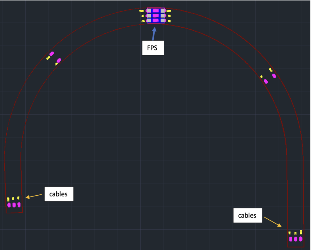
Connect one end of B2-62 (output) to the input of B3-58 by soldering it to the other part of Foled-FB-3P connector as shows in the diagram below:
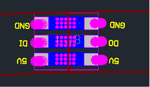
After this process is completed there should be one big piece like this drawing, with cables at both ends and one Foled-FB-3P(FPS) connector board at the middle of the two led boards.
B1-72 (single piece)
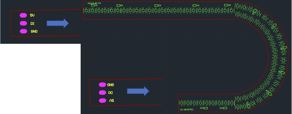
Solder one cable on each pad (5V: red cable, DI/DO: white cable, GND: black cable) pointing to the inside of the board as it shows the blue arrow. Cables should be soldered in both ends of the led board.
Final Assembly
Once all the sets and single pieces are ready. There is only one final process to be done which is to install the pieces as described on this drawing:
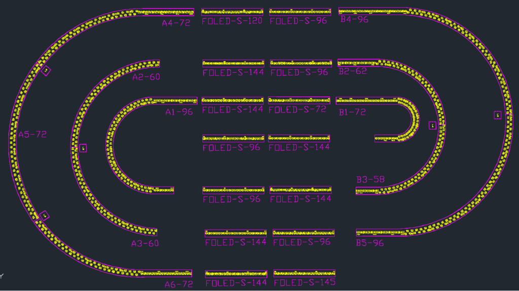
It is very important that each Set is placed in the right position of the board to fit properly the LED harness assembly assistant board to every inch of it.
Note:
Each board has an input and output, so it is very important to make sure that when using Foled-SC-3P to connect the boards, their output and input are connected together, same as ground to ground and 5V to 5V to guarantee proper and safe operation of the harness assembly assistant board.